Adjustable Relay Module – NP-NRM-10
£46.15
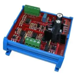
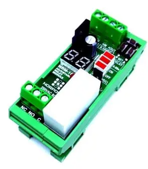
The NRM-10 is a Digital, advanced, feature-rich, compact, and economical adjustable relay module.
⚡ Electrical Calculator
🔌 Cable Size Reference
🌬 Unit Converter
🔋 Transformer VA & MCB Calculator
📊 Reference Guide
| Current (A) | Cable Size (mm²) |
|---|---|
| 6 | 1 |
| 6-12 | 1.5 |
| 12-25 | 2.5 |
| 25-32 | 4 |
| 32-40 | 6 |
| 40-64 | 10 |
| You must consider Ambient Temperature, Location and Thermal insulation in contact with cable. | |
Description
Description
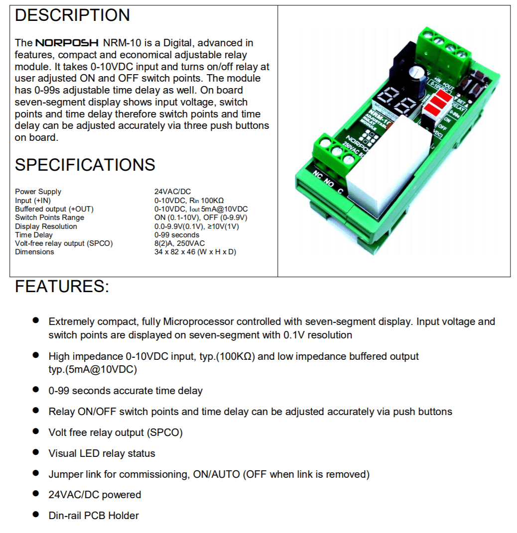
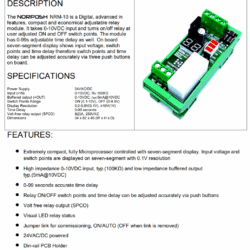
The NRM-10 is a Digital, advanced, feature-rich, compact, and economical adjustable relay module.
It accepts a 0-10VDC input and controls the relay at user-adjusted ON and OFF switch points.
The module also has a 0-99s adjustable time delay.
The onboard seven-segment display shows input voltage, switch points, and time delay; therefore, switch points and time delay can be adjusted accurately via three onboard pushbuttons.
Specifications
| Power Supply | 24VAC/DC |
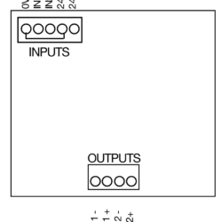
| Input (+IN) | 0-10VDC, Rin 100KΩ |
| Buffered output (+OUT) | 0-10VDC, Iout 5mA@10VDC |
| Switch Points Range | ON (0.1-10V), OFF (0-9.9V) |
| Display Resolution | 0.0-9.9V(0.1V), ≥10V(1V) |
| Time Delay | 0-99 seconds |
| Volt-free relay output (SPCO) | 8(2)A, 250VAC |
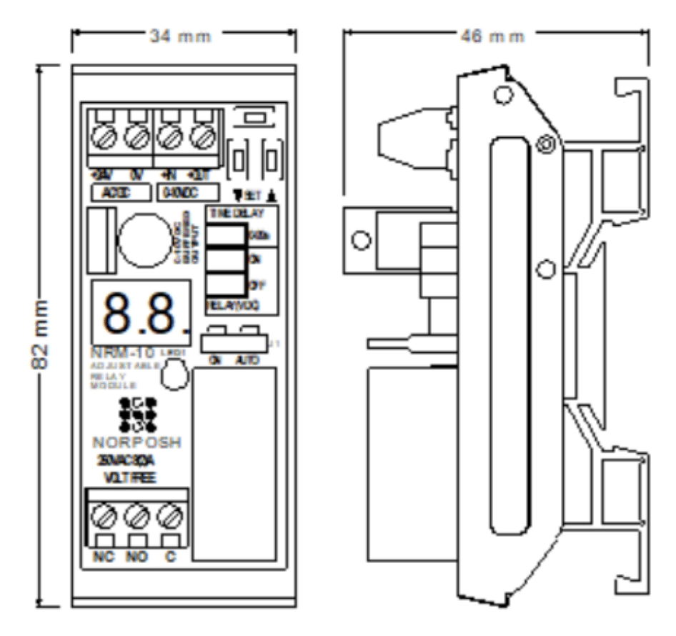
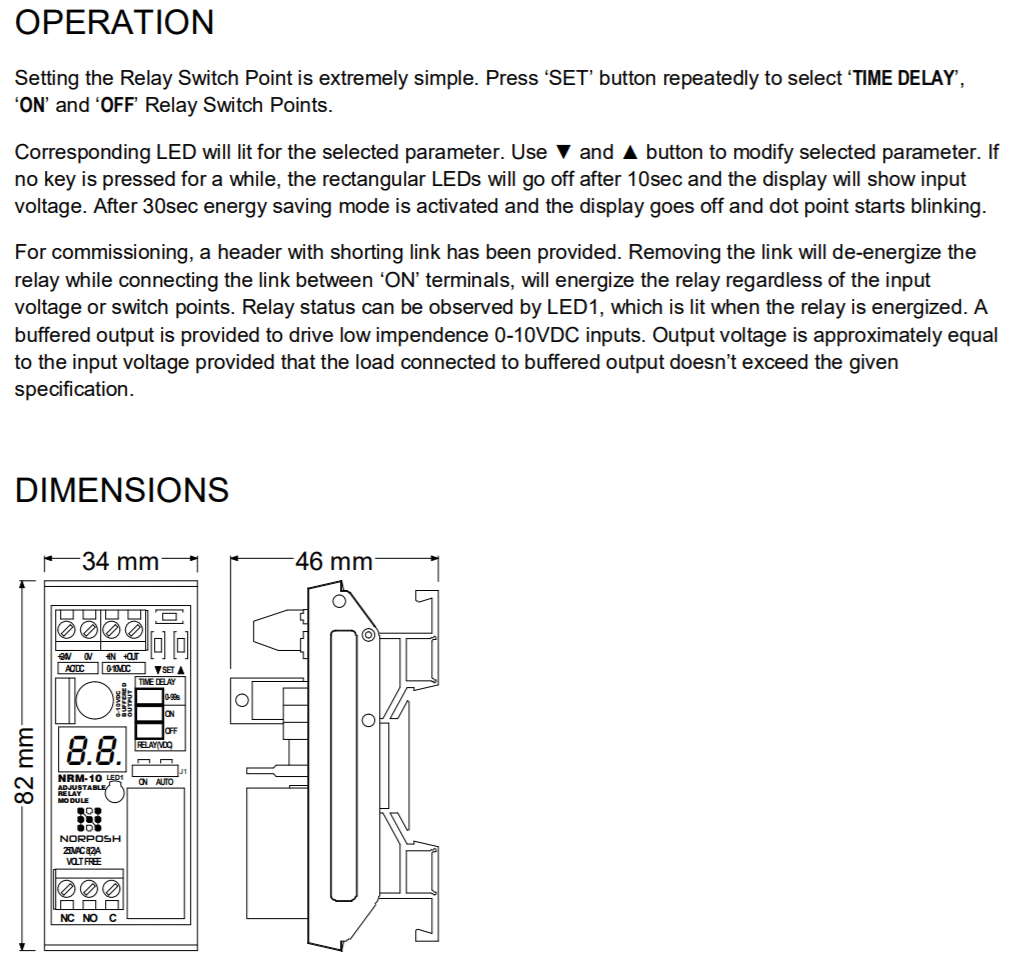
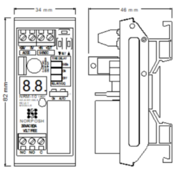
| Dimensions | 34 x 82 x 46 (W x H x D) |
Features
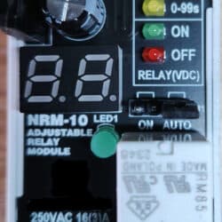
- Extremely compact, fully microprocessor-controlled with the seven-segment display. Input voltage and switch points are displayed on seven segments with 0.1V resolution.
- High impedance 0-10VDC input, typ.(100KΩ) and low impedance buffered output typ.(5mA@10VDC).
- 0-99 seconds accurate time delay.
- Relay ON/OFF switch points and time delay can be adjusted accurately via push buttons.
- Volt-free relay output (SPCO).
- Visual LED relay status.
- Jumper link for commissioning, ON/AUTO (OFF when the link is removed).
- 24VAC/DC powered.
- Din-rail PCB Holder.

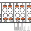
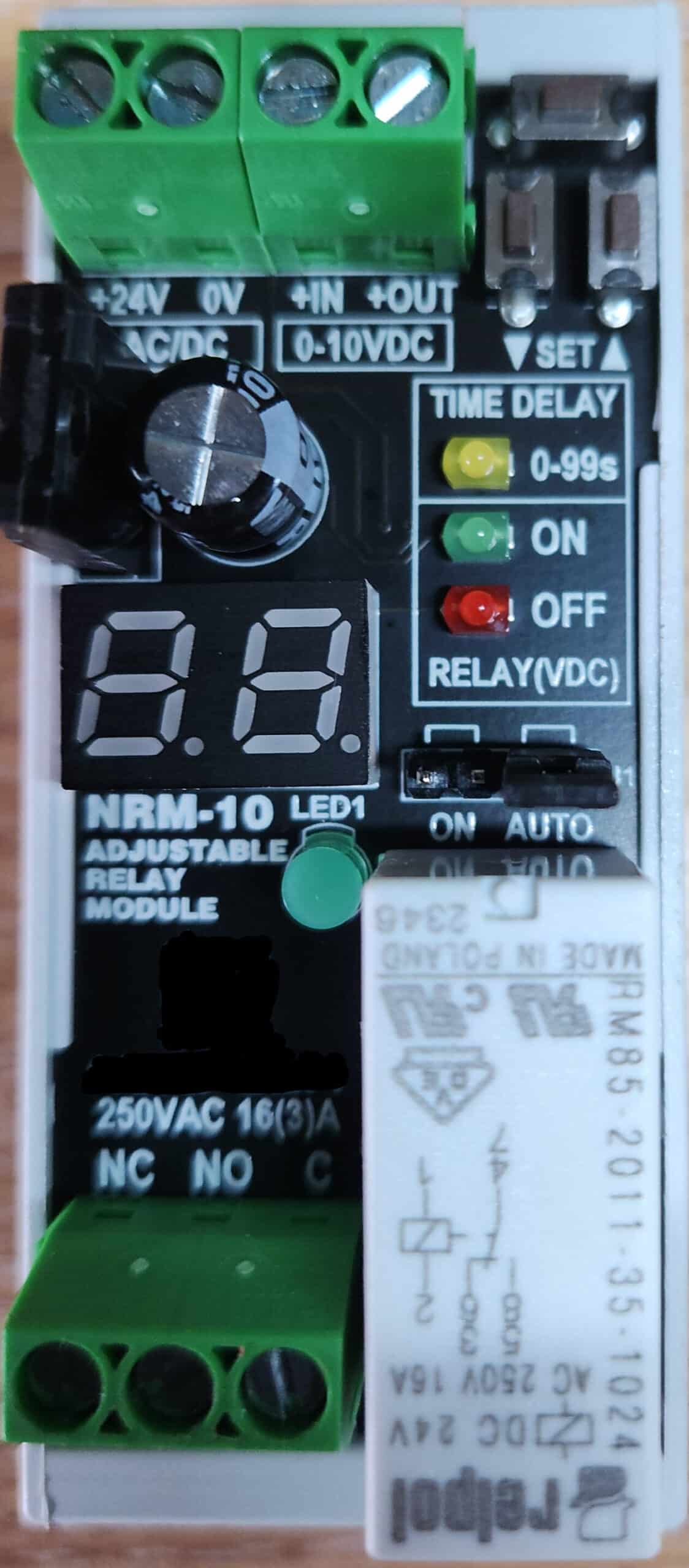
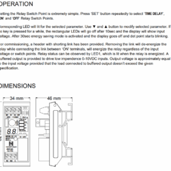
OPERATION
Setting the Relay Switch Point is extremely simple. Press the ‘SET’ button repeatedly to select ‘TIME DELAY’, ‘ON’ and ‘OFF’ Relay Switch Points.
The corresponding LED will be lit for the selected parameter. Use ▼ the ▲ button to modify the chosen parameter. If no key is pressed for 10 seconds, the rectangular LEDs will turn off, and the display will show the input voltage. After 30 seconds, the energy-saving mode is activated; the display turns off, and the dot point starts blinking.
For commissioning, a shortened link header has been provided. Removing the link will de-energise the relay while connecting the link between ‘ON’ terminals, which will energise the relay regardless of the input voltage or switch points. Relay status can be observed via LED1, which lights when the relay is energised. A buffered output is provided to drive low impedance 0-10VDC inputs. The output voltage is approximately equal to the input voltage, provided that the load connected to the buffered output doesn’t exceed the given

Additional information
| Amps |
4A, 6A, 8A |
|---|